This is the PICAXE code used for the buggy on the protoype testing day is shown below. It impliments the use of if....else command. Low's and High's are used to send outputs to the connected components such as the LED's and motors. It also uses sub-routines to keep the code neat and efficient as possible.
symbol switchstate = b0
main:
if switchstate = 0 then
debug switchstate ;used so we can see the state the swith b0 is in
goto program1
else
goto program2
endif
goto main
program1: ;used to follow the track
readadc 1, b1 ;reads and converts the analogue input from left LDR
debug b1 ;used to calibrate the left LDR
readadc 2, b2 ;reads and converts the analogue input from right LDR
debug b2 ;used to calibrate the right LDR
high 5 ;sends an output high to the two LED's
high 6
if b2 > 110 and b1 ;if the left LDR is on white and the right LDR on black
goto right
endif
if b2 <> 110 then ;if the left LDR is on black and the right LDR on white
goto left
else ;otherwise move forwards
goto straight
endif
goto main
program2: ;used to identify the symbols
readadc 1, b1 ;reads and converts the analogue input from left LDR
debug b1 ;used to calibrate the left LDR
readadc 2, b2 ;reads and converts the analogue input from right LDR
debug b2 ;used to calibrate the right LDR
high 5 ;sends an output high to the two LED's
high 6
if b2 > 110 and b1 > 110 then ;if the left LDR is on black and the right LDR on black
low 1 low 2 low 3 low 4 ;stay stationary for three seconds
pause 3000
endif
goto program2
if b2 > 110 and b1 ;if the left LDR is on white and the right LDR on black
goto left ;turn left for three seconds
endif
if b2 <> 110 then ;if the left LDR is on black and the right LDR on white
goto right ;turn right for three seconds
else ;otherwise move backwards
goto back
endif
goto main
straight:
low 1 high 2
low 3 high 4
goto main
right:
low 1 low 2 low 3 high 4
goto main
left:
low 1 high 2 low 3 low 4
goto main
back:
low 2 high 1 low 4 high 3
goto main
Showing posts with label Rajinder Sidhu. Show all posts
Showing posts with label Rajinder Sidhu. Show all posts
Wednesday, 28 April 2010

Tuesday, 27 April 2010
The Completed Buggy
The images below show the completed buggy with all the components connected. They also show the improvements we made, such as the shield which blocks out ambient light. This final buggy also impliments the use of brighter white LED's instead of the red type used earlier. These provide better light and therefore increase the sensitivity of the LDR's. This change has lead to a significant improvement in line following performance.


Buggy Build Update
A couple of improvements have been made to the buggy in order to improve the performance of the line following.
We experienced problems with the LDR's not reading light the way we would have liked it to. Because the LDR's read all visible light, the sensitivity repeatedly changed in different ambient lighting conditions. At one time during testing the LDR's readings changed by 40 from around 100 to 60 when taking the buggy into different rooms. To solve this problem we incorperated the use of a shield which blocked ambient light from reching the LDR's. This shield was made from black card and was assembled around the two sensors. The black card reduces the reflection of the light from the LED's. This means that only light from the LED's is reflected from the white surface to the LDR's, therefore improving the line following performance of the buggy.
We experienced problems with the LDR's not reading light the way we would have liked it to. Because the LDR's read all visible light, the sensitivity repeatedly changed in different ambient lighting conditions. At one time during testing the LDR's readings changed by 40 from around 100 to 60 when taking the buggy into different rooms. To solve this problem we incorperated the use of a shield which blocked ambient light from reching the LDR's. This shield was made from black card and was assembled around the two sensors. The black card reduces the reflection of the light from the LED's. This means that only light from the LED's is reflected from the white surface to the LDR's, therefore improving the line following performance of the buggy.
Monday, 26 April 2010
Line following code ( First programme code)

Following the first test with the LED using the simple program shown in the video of the 1-04-2010, we came up with this first code to programme the buggy to follow the line.
The Above picture shows the first programme code
Analysis of the Programme (CODE).
Including debug in the programme, we wanted to view how the values included in the programme affected the manner in which the buggy will respond. This way it made it easy to adjust and hence modify the programme. Also, we decided to use a combination of "if...then" statements and sub-routines because we found this method of programming much easier to write and simple to undestand.
However, after writing this programme and programming the buggy, we found out a couple of errors with the code. Firstly, we discovered the range of values associated to the LDR (245, above and below) was quite large and the fluctations of the values hardly went up to 245. So making the values much smaller sounded very reasonable. Secondly, because the LDR was affected by the intensity of light at any one time of the day in a room, it was difficult to get a specific and accurate value to assign to the LDR since light conditions were not stable. Lastly, we noticed that whenever the buggy was moving it kept going in a circular path. After careful analysis we realised that the left and right sub-routines were interchanged.
Check out for the new and approved code with new values and improved sub-routines.
Monday, 12 April 2010
Buggy Build Update
Now that the chassis for the buggy is complete we started to mount the breadboard and circuitary.

The breadboard is the largest component, so we have decided to mount it along the top of the chassis in between the two wheels.
The PICAXE project board is mounted above the breadboard to avoid a short circuit. This also improves the aesthetics of the design as it now ressembles a RC Buggy.
The motors are mounted onto the bottom of the chassis in order to keep maximum space available across the top for the breadboard.
The battery back is mounted off the back of the PICAXE project board. The reason for this is so that the wheels have increased traction because of the load being directly over the wheels.
The LED's and LDR's are connected to the front end of the breadboard, in order to keep the circuitary neat. This also means the length of the wires used to connect each component can be shorter.
The sensing system being a fair distance from the motors improves the performence of the buggy. This is because the motors need to turn less when correcting itself whilst following the line. The motor turning less, decreases the angle of correction and would therefore increase the line following speed and accuracy of the buggy.
The breadboard is the largest component, so we have decided to mount it along the top of the chassis in between the two wheels.
The PICAXE project board is mounted above the breadboard to avoid a short circuit. This also improves the aesthetics of the design as it now ressembles a RC Buggy.
The motors are mounted onto the bottom of the chassis in order to keep maximum space available across the top for the breadboard.
The battery back is mounted off the back of the PICAXE project board. The reason for this is so that the wheels have increased traction because of the load being directly over the wheels.
The LED's and LDR's are connected to the front end of the breadboard, in order to keep the circuitary neat. This also means the length of the wires used to connect each component can be shorter.
The sensing system being a fair distance from the motors improves the performence of the buggy. This is because the motors need to turn less when correcting itself whilst following the line. The motor turning less, decreases the angle of correction and would therefore increase the line following speed and accuracy of the buggy.
Saturday, 10 April 2010
Buggy Build Update
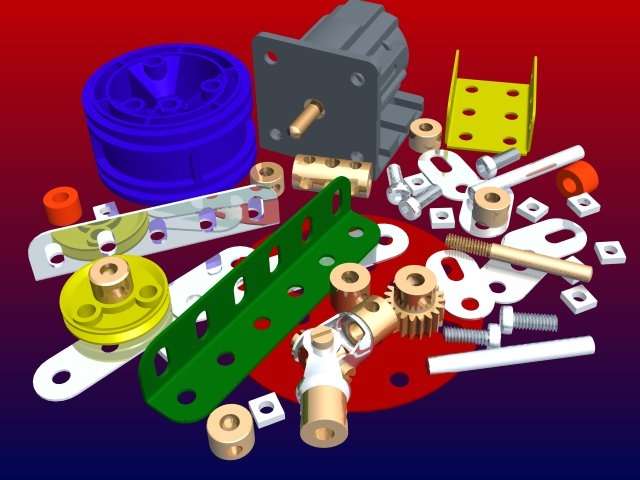
We have now constructed a prototype version of the buggy using some Mechano type hardware bought from 'the entertainer' (no reinburstment Dr Thompson?). We have developed a chassis where the circuit board will be mounted on top and attached the two motors we are using to power the large yellow wheels to the underside of the chassis. For directional stability we have attached a ball that is moveable in all directions, to the front of the design.


Tuesday, 6 April 2010
Manufacture Of The Chassis
The chassis will be used as a base to mount all of the individual components we will be using, such as the wheels, the motors and circuitry.
As a group we thought of many different ideas for the chassis, including the use of lego, acrylic sheet and cardboard. The list was narrowed down as we thought most of these ideas were not feasible for a number of reasons, such as rigidity and being difficult to build.
Three ideas were selected to be feasible, one of them being a used RC buggy chassis and the other two employing the use of meccano and plywood.


The used RC buggy was specifically designed for a purpose by its manufacturer. Hence the holes and mounts on the chassis. If this was selected the holes and mounts would get in the way of our circuitry. The holes also look visually unappealing.
Choosing to manufacturer the buggy chassis using plywood gives us more freedom to change the chassis to fit the circuitry. However, once the chassis has been manufactured to fit it is difficult to adapt it, therefore a new chassis would need to be built.
Using meccano to build the chassis is the most feasible and practical idea because it holds no limitations. If the design of the chssis needs to be changed at any point it can easily be done. Also, meccano would be the most visually appealing chassis out of the three pictured above.
As a group we thought of many different ideas for the chassis, including the use of lego, acrylic sheet and cardboard. The list was narrowed down as we thought most of these ideas were not feasible for a number of reasons, such as rigidity and being difficult to build.
Three ideas were selected to be feasible, one of them being a used RC buggy chassis and the other two employing the use of meccano and plywood.


The used RC buggy was specifically designed for a purpose by its manufacturer. Hence the holes and mounts on the chassis. If this was selected the holes and mounts would get in the way of our circuitry. The holes also look visually unappealing.
Choosing to manufacturer the buggy chassis using plywood gives us more freedom to change the chassis to fit the circuitry. However, once the chassis has been manufactured to fit it is difficult to adapt it, therefore a new chassis would need to be built.
Using meccano to build the chassis is the most feasible and practical idea because it holds no limitations. If the design of the chssis needs to be changed at any point it can easily be done. Also, meccano would be the most visually appealing chassis out of the three pictured above.
Wednesday, 24 March 2010
Using LDR's to track the black line
A line follower robot works on the same principle as a light follower robot. However, instead of tracking light the LDR (Light Dependant Resistor) is used to track the black line. This is done by programming the chip connected to the LDR to differentiate the line colour and the colour of its surroundings (in our case a black line on a white background).

It is possible to use one LDR to act as the sensing device to track the line; however the buggy would not follow the line smoothly. To improve the smoothness (resolution) of the line following, more LDR’s would need to be used.
As we are limited to the number of LDR’s we can connect to our project board the group have made a decision to use 2 LDR’s in a line combination.


Tuesday, 16 March 2010
Project Brief
We are to build and test an intelligent buggy which will have two modes of operation. This mode will be selectable by the use of a switch.
The first operation is for the buggy to follow a line made from a dark magnetic strip of 20mm width. The deviations of the line will be at no more than 45 degrees.
The second operation is for the buggy to read road markings (90 degree turn left, 90 degree turn right and a T-junction) and execute the appropriate motion.
The first operation is for the buggy to follow a line made from a dark magnetic strip of 20mm width. The deviations of the line will be at no more than 45 degrees.
The second operation is for the buggy to read road markings (90 degree turn left, 90 degree turn right and a T-junction) and execute the appropriate motion.
Subscribe to:
Posts (Atom)